
Flexible Bifacial Solar Panels: Design, Output and Uses
Flexible bifacial solar panels generate electricity from both front and rear surfaces, making them useful where reflected or transmitted light can reach the back. Their real advantage depends on mounting height, ground or roof reflectivity, spacing, shading, and rear-side irradiance—not simply the fact that the module is bifacial.
What Are Flexible Bifacial Solar Panels?
Flexible bifacial solar panels combine two characteristics:
- Flexible construction allows the module to follow a suitable curved or lightweight surface.
- Bifacial photovoltaic design allows the rear side to contribute to electricity generation when usable light reaches it.
A conventional monofacial panel mainly uses the front surface. A bifacial module has an active rear side as well. That sounds straightforward until the panel is installed.
The rear side needs light.
If the back of a panel is pressed directly against an opaque roof, there may be very little useful rear irradiance. In that situation, paying for bifacial capability may not translate into a meaningful energy benefit.
This is one of the most important points to establish before specifying flexible bifacial solar panels for an OEM project.
NREL’s bifacial modeling work specifically considers variables such as albedo, module-to-module spacing, clearance height, shading and system geometry because these conditions influence the irradiance reaching the rear of a bifacial module.
How Bifacial Solar Technology Works
The front and rear surfaces of a bifacial photovoltaic module can receive irradiance from different directions.
The front side receives direct sunlight and diffuse sky radiation. The rear side may receive:
- Reflected sunlight from the ground
- Reflected light from a roof
- Diffuse sky radiation
- Light entering through gaps or around the module
- Reflected light from nearby surfaces
The additional energy is commonly discussed as bifacial gain.
But there is no universal bifacial gain percentage that applies to every installation.
NREL research notes that rear irradiance varies with deployment conditions and is affected by factors including self-shading, ground cover and module clearance.
That is why a supplier quoting “up to X% more energy” without describing the test or installation conditions is giving incomplete information.
Flexible Bifacial Solar Panel Output and Bifacial Gain
The cleanest way to think about bifacial output is to separate the front-side contribution from the rear-side contribution.
A simplified relationship is:
Total bifacial energy ≈ front-side energy + useful rear-side contribution − system losses
The rear-side contribution depends heavily on how much irradiance actually reaches the back of the module.
NREL’s published research has reported additional energy gains of 5%–25% under different ground-cover scenarios, while its commercial PV analysis notes that field demonstrations have shown a wider range depending on mounting conditions. These figures are not universal performance guarantees; they illustrate how strongly deployment conditions affect bifacial gain.
Why Albedo Matters
Albedo describes the fraction of incoming solar radiation reflected by a surface.
A dark surface absorbs more sunlight and generally reflects less. A bright surface can send more light toward the rear of a bifacial module.
NREL’s commercial PV analysis gives a useful example: it uses an albedo of 0.3 for a representative condition and notes that a white roof can have an albedo around 0.7.
That does not mean a white roof automatically produces a specific percentage increase.
Roof geometry, panel height, spacing, tilt, shading and surface condition still matter.
The Clearance Behind the Panel
This is particularly important for flexible products.
A flexible bifacial module installed almost flush against an opaque surface may have little opportunity to collect rear irradiance.
A raised installation with an open rear surface is different.
Even a small mechanical design change can alter:
- Rear irradiance
- Ventilation
- Module temperature
- Shading
- Cable routing
- Cleaning access
- Structural loading
NREL’s bifacial modeling toolkit explicitly allows designers to model clearance height, tilt, pitch, reflective surfaces, shading obstructions and module spacing.
For an engineered B2B product, these parameters belong in the early design discussion rather than being left to the installer.
Where Flexible Bifacial Solar Panels Make Sense
The strongest applications are not necessarily traditional residential rooftops.
They are situations where both flexibility and rear-side light availability can exist at the same time.
Potential applications include:
- Raised lightweight solar structures
- Carports
- Canopies
- Specialty architectural PV
- Agricultural structures
- Lightweight off-grid systems
- Certain mobile structures
- Custom OEM equipment
- Semi-transparent or spaced module assemblies
- Reflective-roof installations
The application needs to be assessed carefully.
A curved opaque roof with the panel permanently bonded to the surface may benefit from flexibility but provide limited value from bifacial operation.
A raised canopy with open space beneath the module is a different proposition.
Flexible Bifacial Solar Panels for RVs
RV applications require particular care.
An RV roof provides a strong argument for lightweight flexible construction. However, a typical bonded installation places the rear of the module close to the roof surface.
That creates a design question:
Where will the rear-side irradiance come from?
If the module is mounted directly on an opaque white or light-colored roof, some reflected light may reach the rear depending on the module construction and spacing. But if the rear is effectively blocked, the bifacial advantage can be greatly reduced.
For an RV, a monofacial flexible panel may therefore be the more straightforward configuration in some designs.
For a custom OEM vehicle system, the answer should come from a layout and irradiance assessment rather than the product name.
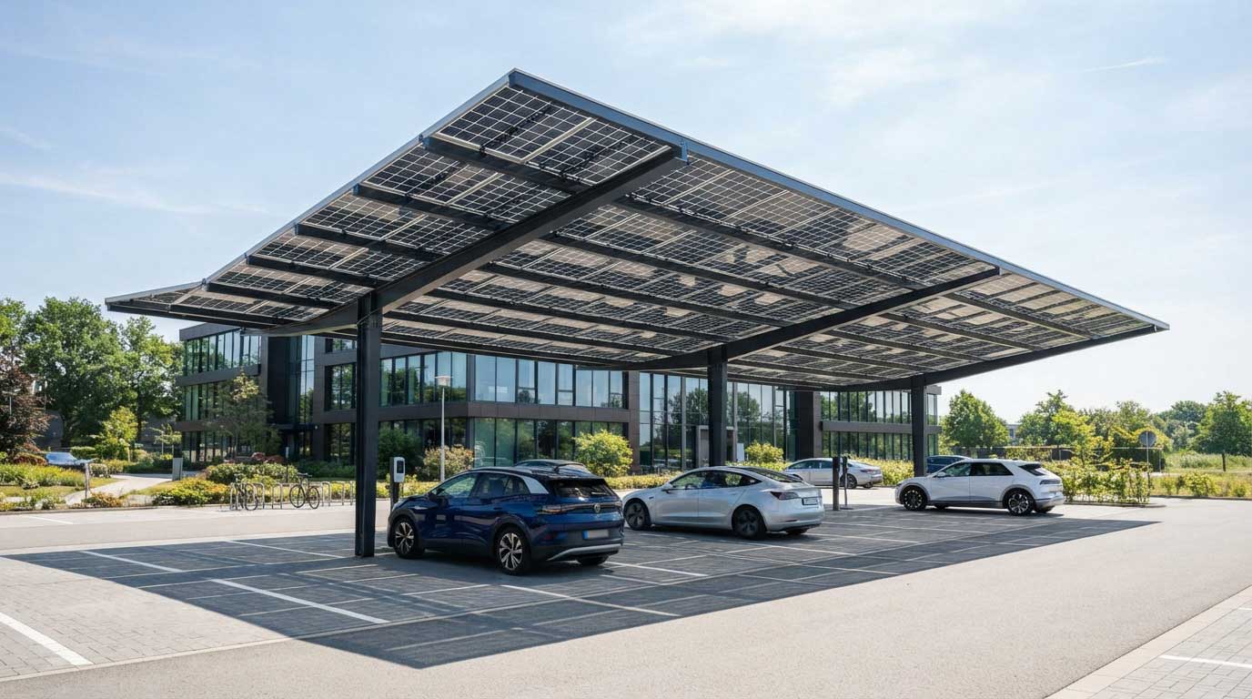
Canopies, Carports and Raised Structures
This is where bifacial technology becomes more intuitive.
A bifacial module installed above a carport has open space behind it. Light reflected from the pavement or surrounding surfaces can reach the rear.
A lightweight flexible construction may also help when the structure has unusual geometry or when reducing module weight is part of the design requirement.
Flexible Bifacial vs. Monofacial Flexible Solar Panels
The decision is not simply “bifacial produces more.”
The more useful comparison is whether the installation provides enough rear irradiance to justify the additional module design requirements.
| Factor | Flexible Monofacial | Flexible Bifacial |
|---|---|---|
| Front-side generation | Yes | Yes |
| Rear-side generation | No meaningful active contribution | Yes, when rear irradiance is available |
| Direct roof bonding | Usually straightforward | Can limit rear-side benefit |
| Raised installation | Suitable | Particularly useful |
| Reflective surface | Less important | More important |
| Clearance | Mainly mechanical/thermal issue | Also affects rear irradiance |
| System modeling | Useful | Especially important |
| Best use case | Conventional curved surfaces | Curved/raised designs with rear light |
For a simple curved RV roof, flexibility may be the primary requirement.
For a raised canopy, bifacial capability may become much more significant.
For a custom product, these two requirements should be considered separately.
Key Specifications to Check Before Buying
A product page showing “bifacial flexible solar panel” is not enough for a technical purchasing decision.
Electrical Specifications
Request:
- Rated power
- Voc
- Vmp
- Isc
- Imp
- Front-side test conditions
- Rear-side test conditions
- Bifaciality factor
- Temperature coefficients
- Connector specification
- Maximum system voltage
One important detail is the power-rating methodology.
NREL research has pointed out that one-sun power ratings for bifacial modules have historically lacked a single universal definition because rear irradiance is not represented by the conventional front-side 1,000 W/m² condition alone.
IEC has subsequently developed dedicated measurement procedures for bifacial photovoltaic devices. The current IEC TS 60904-1-2 describes methods for measuring I-V characteristics of bifacial PV devices under natural or simulated sunlight.
For procurement, ask the supplier exactly how the quoted bifacial performance was measured.
Mechanical Specifications
For a flexible module, also check:
- Overall dimensions
- Thickness
- Weight
- Minimum bending radius
- Permitted bending direction
- Static versus dynamic bending
- Mounting method
- Substrate material
- Encapsulation
- Junction-box location
Do not assume that “flexible” means repeatedly foldable.
A module designed to conform to a curved surface may have completely different mechanical limits from a Portable Solar Panel designed for repeated handling.
Installation Steps for Flexible Bifacial Solar Panels
Step 1 — Map the Surface
Measure the complete installation area.
Mark:
- Roof edges
- Curved sections
- Vents
- Drains
- Structural supports
- Cable exits
- Shaded areas
- Maintenance zones
For a custom OEM project, a CAD drawing is preferable to a rough measurement.
Step 2 — Determine Rear-Side Exposure
Stand at the intended installation location and look at the rear side of the proposed module.
What can it actually “see”?
A roof, wall or structural frame can block reflected light.
If the module is elevated, measure the clearance.
If it is installed above a bright surface, record the surface type and approximate coverage.
This information can then be used in a bifacial simulation. NREL’s bifacial_radiance toolkit is specifically designed to model array geometry, reflective surfaces, shading, clearance and spacing.
Step 3 — Check the Mounting Surface
For bonded flexible panels, surface preparation becomes part of the installation engineering.
The surface should be:
- Clean
- Dry
- Structurally sound
- Free of loose coatings
- Compatible with the selected bonding system
For raised systems, inspect the support spacing and avoid creating localized stress points across the flexible module.
Step 4 — Plan Electrical Routing
Before permanent installation:
- Position the module.
- Confirm connector orientation.
- Route the cable.
- Check bending around cable exits.
- Keep connectors away from standing water.
- Verify the series/parallel configuration.
- Confirm charge-controller or inverter limits.
Then complete the permanent installation.
This dry-fit stage takes little time and can prevent much more expensive rework.
A Practical B2B Case: Lightweight Solar Canopy
Consider a hypothetical OEM project for a European parking-canopy manufacturer.
The structure is designed around lightweight steel framing. The engineering team initially considers conventional rigid bifacial modules.
The modules provide the required electrical output, but the design team identifies a weight and architectural issue. The canopy also has a light-colored surface beneath the modules, creating potentially useful rear-side reflected irradiance.
Instead of evaluating the panel only by nameplate wattage, the project team measures:
- Module weight
- Structural loading
- Module spacing
- Rear clearance
- Surface reflectivity
- Cable routing
- Shading
- Annual solar resource
- Maintenance access
A bifacial model is then used to estimate rear irradiance under the actual geometry.
That is a more credible procurement process than applying a fixed “10%” or “20% bifacial gain” to the front-side rating.
The interesting engineering detail is that the structure underneath the panel can be almost as important as the panel itself.
A poorly spaced support system can shade the rear. A low-clearance design can restrict rear irradiance. A dark surface can reflect less light than expected.
Bifacial performance is a system property, not merely a module-label property.
Quality and Certification Considerations
For B2B procurement, certification should be checked against the actual module construction and application.
IEC 61215-1:2021 covers design qualification and type approval for terrestrial PV modules and specifically includes requirements addressing bifacial PV modules. It also includes a bending test for flexible modules.
IEC 61215-2:2021 similarly includes test methods for bifacial PV modules and flexible modules, including the MQT 22 bending test.
This matters because “flexible” and “bifacial” create two separate technical questions:
Can the module withstand its intended mechanical conditions?
Can its bifacial electrical characteristics be measured and qualified appropriately?
For an OEM project, request the relevant test reports and certificates rather than accepting a general statement that the product is “IEC tested.”
Common Mistakes When Choosing Flexible Bifacial Solar Panels
Mistake 1 — Assuming Bifacial Always Means More Energy
Without rear irradiance, the second active surface has little opportunity to contribute.
Mistake 2 — Ignoring Installation Height
Rear-side exposure changes with clearance.
Mistake 3 — Using a Generic Bifacial Gain Percentage
A figure from one field installation should not automatically be applied to another.
Mistake 4 — Bonding the Panel Before Checking the Rear Surface
If the product relies on rear-side illumination, the mounting design needs to be reviewed first.
Mistake 5 — Comparing Different Rating Conditions
Check whether competing products use the same irradiance assumptions and bifacial test methodology.
Mistake 6 — Treating Flexible Construction as a Folding Feature
Check the actual bending specification supplied by the manufacturer.
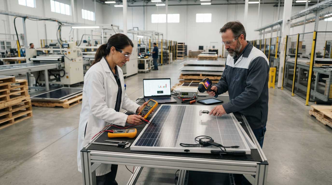
Bright Solar Flexible Solar Panel Solutions for OEM and ODM
Bright Solar develops flexible and semi-flexible solar panel solutions for B2B applications including RVs, campers, outdoor power, selected marine applications and off-grid systems.
For a custom project involving flexible bifacial solar panels, the engineering discussion should begin with the application rather than a predetermined wattage.
Key project information includes:
- Required output
- Module dimensions
- Available surface area
- Curvature
- Rear-side clearance
- Surface reflectivity
- Installation method
- Cell technology
- Electrical configuration
- Weight target
- Connector requirements
- Expected order quantity
- OEM/ODM customization requirements
Bright Solar’s existing flexible-panel portfolio should not be assumed to have bifacial characteristics unless the specific model datasheet confirms them. For a new or customized bifacial design, the module architecture, rear-side exposure and required testing should be established during development.
That is particularly important for buyers who need a product that will be integrated into another company’s equipment or structure.
Flexible Bifacial Solar Panels for Specialized Off-Grid Systems
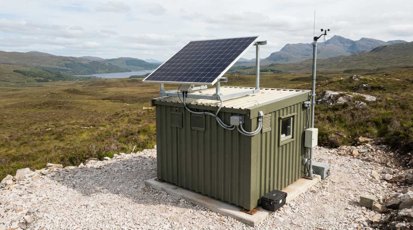
A second useful application is a lightweight off-grid structure where the module is mounted above a reflective or partially open surface.
Imagine a remote monitoring shelter with a shallow canopy.
The solar module is elevated rather than glued directly to the roof. The ground beneath is relatively bright. The rear surface remains exposed. There is enough space for air movement and cable routing.
Here, the bifacial design has a real physical opportunity to work.
Contrast that with the same module bonded tightly to a dark opaque roof.
The product has not changed.
The installation has.
That difference is easy to overlook in product comparisons and is one reason field conditions should be part of the specification process.
FAQ About Flexible Bifacial Solar Panels
What are flexible bifacial solar panels?
Flexible bifacial solar panels are modules designed to generate electricity from both front and rear photovoltaic surfaces while using a flexible module construction suitable for appropriate curved or lightweight installations.
Do flexible bifacial solar panels produce more power?
They can produce additional energy when the rear side receives useful irradiance. The amount depends on installation geometry, albedo, clearance, shading, spacing and weather conditions. NREL research demonstrates that bifacial gains vary significantly between deployment conditions.
Can flexible bifacial solar panels be installed directly on a roof?
They can be physically installed on suitable roofs if the product is designed for that mounting method, but direct bonding against an opaque surface can reduce the rear-side light available to the module. The installation should therefore be evaluated before choosing bifacial technology.
What is bifacial gain?
Bifacial gain is the additional energy generated from rear-side irradiance compared with the front-side output under a defined reference or installation condition. It is not a fixed percentage for every project.
Does a white roof improve bifacial solar performance?
A reflective roof can increase rear-side irradiance compared with a darker surface, but the actual gain also depends on module height, geometry, shading, surface coverage and other site conditions. NREL notes substantially different albedo values for representative dark and white surfaces.
Are bifacial flexible solar panels suitable for RVs?
They can be suitable for specialized RV designs, but a directly bonded roof installation may limit rear-side exposure. For many RV applications, the mechanical advantages of flexible construction may be more important than bifacial operation.
What should an OEM buyer ask a flexible bifacial solar panel manufacturer?
Ask for front and rear electrical specifications, bifaciality information, test conditions, bending limits, dimensions, weight, encapsulation details, environmental testing, certification, warranty and recommended mounting geometry. For bifacial products, also ask how rear-side performance was measured.
Conclusion
Flexible bifacial solar panels are most interesting when two conditions exist together: the installation benefits from a flexible module, and the rear surface can receive useful light.
That makes mounting design unusually important.
A raised canopy, lightweight structure or specialized OEM system can provide a much better environment for bifacial operation than a panel bonded directly to an opaque roof. Albedo, clearance, spacing and shading should therefore be considered during product development, not after the module has already been selected.
For Bright Solar B2B projects, the practical starting point is the complete application: dimensions, curvature, weight, electrical target, mounting method and rear-side exposure. From there, the appropriate flexible module architecture and customization requirements can be evaluated without assuming that one bifacial specification fits every installation.
Related recommendations
-

Flexible 200W Solar Panel: Output, Uses and Installation Guide
128A flexible 200W solar panel can suit selected RV, marine, and off-grid systems, but actual output depends on sunlight, temperature, shading, orientation, and...
View details -
120 Watt Flexible Solar Panel: Lightweight Solar Solution for Mobile Power
138Discover the 120 watt flexible solar panel from Bright Solar. Learn how lightweight solar technology delivers reliable energy for RVs, boats, camping, and off-grid applications.
View details -
Camping Folding Solar Panels: How to Choose and Use Them
62Camping folding solar panels provide portable electricity for outdoor devices and power stations. Choose based on daily energy needs, sunlight, carrying weig...
View details -
Best semi flexible solar panels: A Complete Guide for RV, Marine and Off-Grid Applications
196Explore the best semi flexible solar panels for RV, marine, and off-grid systems with expert advice, performance data, installation insights, and Bright Solar experience.
View details